Abstract
A new modeling technique for SharePoint using standard UML diagrams. The technique will be addressed as an architect tool for SharePoint during implementation and deployment of SharePoint Applications.
Introduction
Microsoft SharePoint is a server product targeted for the collaboration between business owners, researchers, and employees. Its target is to clearly help the organization structure, documents, and process flow to be shared into one organized location.
This location is then managed and moderated by a group of selected users in the firm that strictly speaking (the ones who are aware of the business requirements to the organization)
This article will discuss a modeling technique for SharePoint Applications (developed during the work with SharePoint 2007).
Although the article will give a decent definitions of SharePoint concepts, but a little experience of SharePoint will be helpful to continue reading this Article.
SharePoint Provisioning Containers
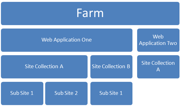
Figure 1: Typical SharePoint hierarchy Relation
Farm
The SharePoint farm is the biggest conceptual entity in the SharePoint hierarchy model. Farm is the container to all web servers, and sql servers that synchronize the content between all of resources together.
Web Application
The SharePoint web application (Encapsulated in SPWebApplication) is a direct representation to the port number beside the http address protocol for example (http://HeavyPoint:5000).
When you create a web application you actually should keep the following items in mind:
- Application Database.
- Application Security.
-
Sub Web applications that help in interfacing for
- Internet
- Extranet
- Intranet
- Application Configurations (web.config)
Site Collection
The second conceptual entity under SharePoint is the Site Collection.
Site collection is the entry point for development under SharePoint.
By creating site collection please keep in mind:
- Sub Sites Container
- Global Features (Per Site Collection)
- Variation Root. (This is the multi-cultural support under SharePoint.)
Sub site
The minimum conceptual container of SharePoint and the exit point for development. Sub sites has the same anatomy of Site Collection however they have their private settings that is not shared among other sites also they inherit their site collection parent settings.
UML (Unified Modeling Language) Diagrams
UML introduced to us a lot of diagrams that theoretically can be used to describe any software architecture. The special stereo type of UML is the key point of describing the SharePoint Provisioning.
Therefore we are going to introduce the important diagrams that we are using in this article (I’ll assume that the reader does know the class diagram, so I will not mention its usage here)
Component Diagram
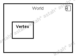
Figure 2: Component Diagram with one Component.
The Component diagram is a container for a lot of other UML entities. Figure 2 illustrate a component called World have inside it a Vertex class.
Components actually in my opinion don’t have a specific 1 to 1 scenario to describe its usage. However we can describe the component by characteristics as:
- The minimum executable entity that can be plugged in and out to the application.
- Standalone object modules.
- Hold a complete implementation to specific functionality.
- Can’t be used independently out of the host application.
From these characteristics Components concept can be expanded to hold component in component mechanism. A sample of components is DirectX, Servlets, ActiveX, and Flash Objects.
Deployment Diagram
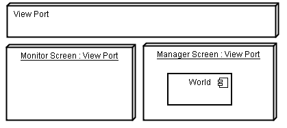
The deployment diagram is a valuable diagram to describe where a specific thing will be put (provisioned)??
The deployment diagram is a collection of physical or nearly physical locations that can be stated, categorized and documented.
SharePoint Definition vs. Provision
The difference between Definition and Provision in SharePoint is the same as the difference between declaring a class and using objects of these classes in the programming language.
Samples of definitions are
- List Definition
- WebPart Definition
- Content Types
- Site Columns
- Site Definition
- Workflow Definition
Provisioning in SharePoint is the Process of putting SharePoint Definitions into their appropriate containers in SharePoint. And the center entity that contains all definitions together is the SharePoint Features.
SharePoint Feature
SharePoint Feature is the minimum deployable entity that can be enabled on the site or sub site level. The Feature contains schemas of definitions.
When you enable a feature over a site it takes all the schemas inside it and tries to put it inside the site or the site collection. Features include any selected numbers of List definitions, web parts, and workflows.
Features has a receivers that perform specific behavior while installation and activation
Features have 4 specific operations:
- Installation (Transfer the Feature Files from File System into the content database)
- Activation (The Feature is provisioning its contents into the site that it was activated into, and execute the receiver activation code)
- Deactivation (opposite of activation)
- Uninstallation (Remove the Feature Files from the Database)
Provisioning Modeling
Now after we’ve reviewed SharePoint Concepts and the Required UML Diagrams we can jump into the modeling technique itself.
As we mentioned before the SharePoint Feature is the main entity that control the provisioning, so it is certainly the most suitable to choose as a starting point of our solution.
Table 1: Representation of SharePoint Entities in UML
| SharePoint Definition | UML Representation | Stereo Type |
| List Definition | Class Shape | <<SPList>> |
| List Provisioning | Object Shape | |
| WebPart | Class Shape | <<WebPart>> |
| Site Column | Class Shape | <<SPSiteColumn>>
<<Type=”Image, Text, or etc.>> |
| Content Type | Class Shape | <<SPContentType>> |
| Feature | Component Shape | <<Scope=Site, Web, or Farm>> |
And by employing the UML diagram rules to the relations between types (association, and aggregation) we can form a relation between Content Type and List Object or Site Column and Content Type or List Definition
UML Representation Example
Let us assume that we have a List hold two Content Types and one site column, one of the content types depend on other site columns.
NOTE: Lists in SharePoint may have multiple Content Types (like publishing feature with Pages List)
Component Diagram
First we draw a component diagram for the feature that tells us “What in the feature?”

Figure 3: Feature as a Component
The diagram actually tells us a lot of information about the feature called “Press Publishing Feature”. It tells us that there is list definition called ArticlesList with two content types Press Page, and Critic Page.
Also the custom Site Columns that we’ve created are actually appearing in the component diagram which increases the illustrative aim of the diagram.
With this simple representation to the feature content, we can now leverage the potential of this technique in modularizing our SharePoint features and their contents
However we still lake very important information!! Where all of these contents will go when we activate this feature?? The answer simply lies in the next lines.
Feature Activation (Deployment Diagram)
Every feature in SharePoint has a time of activation. When we activate the feature it takes its contents from the content database and read the xml files inside it and begin to distribute its contents based on the developer will.
This can be illustrated with the following UML deployment diagram
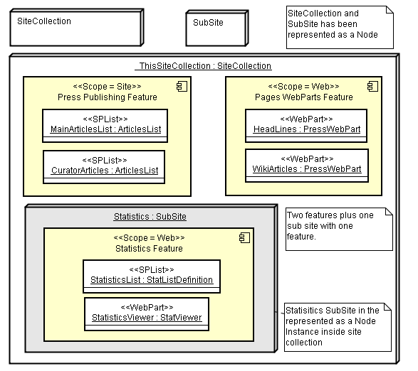
Figure 4: Deployment of Features
The diagram really describes the provisioning schema of the features of this Sample SharePoint Application.
We can see clearly that there are a SiteCollection “_ThisSiteCollection” with Two Features
- Press Publishing Feature
- Pages WebParts Feature
Also a subsite called “Statistics” which has another feature activated in it “Statistics Feature”
In the Statistics Feature Note that we put two instances shapes that represent what will the feature provision when activate.
In order
-
Press Publishing Feature Provision
- MainArticlesList of the list definition ArticlesList
- CuratorArticles of the list definition ArticlesList
-
Pages WebParts Feature Provision two webparts with the same definition
- HeadLines
- WikiArticles
-
Statistics Feature Provision
- StatisticsList of the list definition StatListDefition
- StatisticsViewer of StatViewer WebPart definition
Summing all concepts together we can state clearly that every Feature should have two diagrams
- Component Diagram: responsible of describing “WHAT IN THIS FEATURE??”
- Deployment Diagram: responsible of describing “WHERE TO PUT ITS CONTETNS??”
Conclusion
By answering the two questions of Feature (What and Where). We feel confident about our approach in describing the intent of feature among features inside custom SharePoint Application.
As SharePoint product now is entering its 2010 version, organizations are ready for more adoption to this technology. However the lake of a clear modeling of what is required to build a successful SharePoint application that Business Owners, Developers, and Decision makers can sense and measure its usefulness, increase the barrier of using SharePoint in the right direction.
By introducing a modeling technique based on standard UML notation, we think that this step will leverage more potential of SharePoint and its usage.
Also this technique encourages the description by business perspective more than development perspective which can be positioned as a middle representation for all parties involved in SharePoint development.
By this contribution to the SharePoint community we wish to see more complex scenarios that simplified by this technique and to help developers to think about architecture before webpart implementation. Also to encourage the complete views for solutions not partial views that always lake the illustrative understanding of the desired functionality.